Project background
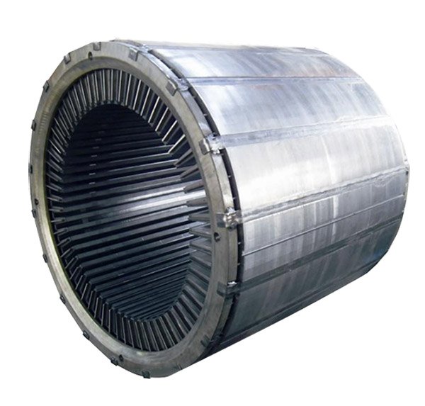
The stator core of large generators is mainly made of silicon steel stamped and laminated. During the core manufacturing process, due to factors such as damage to the insulation layer or burrs, short circuits occur between the core layers, resulting in local temperature rise and air voids in the core during operation. The load loss increases, affecting the normal operation of the generator.
Needs analysis
The customer requested that the magnetic core loss of the generator stator core be measured, and the test reflect the possible hot spots in the hole in the stator core, so as to evaluate the quality of the magnetic core.
Solution
1. Test equipment
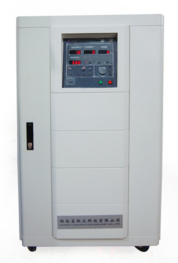
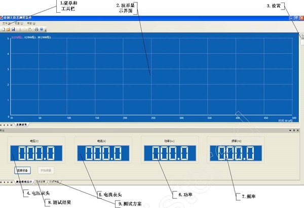
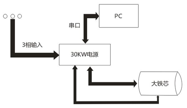
The test device uses a high-power output (maximum output power 30kw, maximum output current 300A) power supply to measure the no-load current and core loss (primary) of the iron core under industrial frequency conditions. The power supply is controlled and read through software on the PC. , PC software has functions such as automatic measurement, real-time display of test data, storage of test results, and storage of test plans.
The device is used with an infrared temperature tester to measure the temperature rise of various parts of the hole in the stator core.
2. Measurement principle
3. Measurement parameters
Coil turns
Test voltage
Current calculation
Iron loss calculation
4. Iron core test
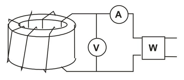
5. Operation steps
Test core iron loss
Iron core hot spot analysis: Place the iron core under a magnetic induction intensity of 1.5T (continuous power on) for 30 minutes, and use an infrared thermometer to detect the temperature changes at different positions on the inner wall of the core hole.
6. Software interface
